


High voltage high frequency dc solid state relay
Home Products DC to DC Solid State RelayDC output solid state relayHigh voltage high frequency dc solid state relay


High voltage high frequency dc solid state relay
- Optical-magnetic coupling isolation between input and output circuits.
- Control signal interfaces with PLC, TTL, PWM signals.
- LED indicator for working status.
- Solid-state, contactless switch output, no sparks or arcing during switching.
- Built-in protection features for under-voltage, over-voltage, and over-temperature.
- Encapsulated in epoxy resin, providing corrosion resistance, shock resistance, and reliable operation.
- The product is mainly used for industrial control of DC high-voltage, high-current, high-power switching electrical equipment.
| Part numbers |
GDZ08GY; GDZ08GD (for inductive load) |
|---|---|
| Control Voltage | 12 to 15VDC, 18 to 36VDC |
| Control Current | 60 to 160mA, 50 to 140mA |
| Under-voltage Protection | Self-lock at <10VDC for 12V supply, Self-lock at <16VDC for 18V supply |
| Operating Indicator | LED |
| Switching Time | ≤ 0.45ms |
| Maximum Voltage | 2400V |
| Maximum Current | 20 to 200A |
| On-state Voltage Drop | ≤ 8.8V |
| Off-state Voltage | ≥ 2400V |
| Over-voltage Protection | Transient 2000V |
| Over-temperature Protection | 100°C |
| Isolation Voltage | ≥ 2500V |
| Insulation Voltage | ≥ 2500V |
| Operating Temperature | -30 to 75℃ |
| Power Frequency | 10 to 1000Hz |
| Cooling Conditions | Heat sink with fan required |
| Load Current Safety Factor | Resistive load: 2-3 times, Inductive load: 3-4 times of load current |
 |
 |
| Part numbers | GDZ08CGY;GDZ08CGD (for inductive load) |
|---|---|
| Control Power Supply | 12 to 15VDC/2W, 18 to 36VDC/2W |
| Control Voltage | 4 to 32VDC |
| Control Current | 10 to 25mA |
| Operating Indicator | LED |
| Switching Time | ≤ 0.25ms |
| Maximum Voltage | 2400V |
| Maximum Current | 20 to 200A |
| On-state Voltage Drop | ≤ 8.8V |
| Off-state Voltage | ≥ 2400V |
| Over-voltage Protection | Transient 2000V |
| Over-temperature Protection | 100°C |
| Isolation Voltage | ≥ 2500V |
| Insulation Voltage | ≥ 2500V |
| Operating Temperature | -30 to 75℃ |
| Power Frequency | 10 to 1000Hz |
| Cooling Conditions | Heat sink with fan required |
| Load Current Safety Factor | Resistive load: 2-3 times, Inductive load: 3-4 times of load current |
 |
 |
Since the load voltage of a DC solid-state relay is equal to its off-state voltage, and the load current is at its maximum value at room temperature, a margin should be left when selecting one. For resistive loads: the current should be chosen at 2.5 to 4 times the load current, and the voltage should be chosen at 2 to 3 times the load voltage. For inductive loads: the current should be chosen at 4 to 6 times the load current.
The actual load current is greatly related to the ambient temperature. When the ambient temperature is high or the cooling conditions are poor, the current capacity should be increased. To prevent a load short circuit during use, it is required to add an overload protector in the load circuit.
For inductive loads, the GDZ08GY/GDZ08CGY model must have a flyback diode connected across both ends of the load to prevent damage to the solid-state switch by over-voltage. The GDZ08GD/GDZ08CGD model has an integrated flyback diode, so it can be used directly with inductive loads without adding a separate flyback diode.
The heat sink that comes with this product must have a flat and clean contact surface, and a layer of thermal conductive silicone grease should be applied to its surface. When fixing, screws should be tightened symmetrically with spring washers and flat washers to prevent loosening due to thermal expansion and contraction.
- High frequency dc solid state relay, the application and features you may know.
- DC solid state relay and DC contactor, which one is better?
- Solid-state relay parameter terms explanation in English.
- Applications and Customization Services of DC Solid State Relays
- How to choose a suitable Solid State Relays
What Do High Frequency and Low Frequency Mean in DC Solid State Relays, and What Are the Differences?
High frequency and low frequency in DC solid state relays (DC SSR) refer to the frequency at which the relay can switch the circuit, i.e., the number of times the relay can open and close within a unit of time. The differences between high frequency and low frequency are mainly reflected in the following aspects:
Switching Speed:
High Frequency: High-frequency solid state relays can complete switching operations in a very short time, usually at the millisecond or even microsecond level. This makes them suitable for applications requiring rapid response, such as pulse modulation and fast power switching.
Low Frequency: Low-frequency solid state relays have a slower switching speed and are suitable for applications that do not require frequent switching, such as general power control and heater control.
Application Scenarios:
High-Frequency Applications: Suitable for scenarios requiring fast switching, such as communication equipment, automation control systems, and audio equipment.
Low-Frequency Applications: Suitable for scenarios with lower switching frequency, such as lighting control and simple motor start and stop.
Thermal Management:
High Frequency: Due to frequent switching operations, high-frequency solid state relays may generate more heat, requiring better thermal design.
Low Frequency: Generates relatively less heat due to lower switching frequency, thus having lower thermal management requirements.
Electromagnetic Interference (EMI):
High Frequency: High-frequency switching may generate more electromagnetic interference, requiring additional measures to suppress EMI.
Low Frequency: Relatively less electromagnetic interference, making the design simpler.
Lifespan and Reliability:
High Frequency: Frequent switching operations may pose higher demands on the device's lifespan and reliability.
Low Frequency: Due to fewer switching operations, they generally have a longer lifespan and higher reliability.
In summary, the choice between high frequency and low frequency DC solid state relays depends on specific application requirements, including response speed, thermal management, and electromagnetic compatibility.
Need more information?
Contact us to request pricing, availability and customization options.

DC Solid State Relay built in Freewheeling Diode (GDZ06)
60A to 200A, 100V to 1200VDC, Built in Freewheeling Diode DC SSR, recommend for inductive load.
View More
GDZ09 DC to DC high current solid state relay
600A to 2000A, 100V to 1200VDC
View More
Three channel output dc solid state relay (GDZ033)
30-200A, 100V to 1200V, 3 channel ouput dc ssr.
View More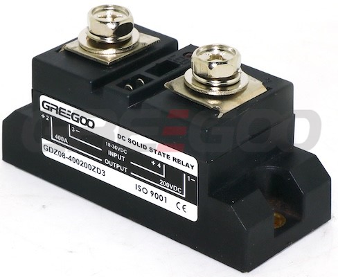
DC Solid State Relay - 120A to 2000A 100V to 1200V
DC:120 - 2000A, 100 to 1200VDC DC load solid state relays.
View More

