


Solid-state relay parameter terms explanation in English.
Solid-state relay parameter terms explanation
-
Control Voltage Range: The range of voltage applied to the input terminal that allows the solid-state relay to operate normally under specified environmental temperatures. For resistive input type, the input voltage range is generally 4-16V; for constant current input type, it is mostly 3-32V; and for AC input type: 90-250VAC.
-
Input Current: The current value flowing into the input circuit of the solid-state relay at a specific input voltage under specified environmental temperatures.
-
Turn-on Voltage: The minimum voltage applied to the input terminal to ensure the normally open solid-state relay output circuit is connected. It is similar to the maximum action voltage of an electromagnetic relay. This value is generally the lower limit of the solid-state relay's input voltage range. When this voltage or a higher voltage is applied to the input terminal, the solid-state relay is guaranteed to turn on.
-
Turn-off Voltage: The maximum voltage applied to the input terminal to ensure the normally open solid-state relay output circuit is disconnected. It is similar to the minimum release voltage of an electromagnetic relay. When this voltage or a lower voltage is applied to the input terminal, the solid-state relay is guaranteed to turn off.

-
Reverse Voltage: The maximum allowable reverse voltage that can be applied to the input terminal of the solid-state relay without causing permanent damage. This value is generally determined as the upper limit of the input voltage range.
-
Load Current Range: The maximum steady-state load current value that the solid-state relay can handle under specified environmental temperatures. It is generally a nominal value, and the allowable maximum output current decreases when the ambient temperature rises above 40°C. Therefore, a margin is left depending on the nature of the load. A minimum load current is also specified, generally 50mA.
-
Load Voltage Range: The maximum steady-state load voltage that the solid-state relay can withstand under specified environmental temperatures. It should also specify the minimum output voltage at which the solid-state relay can normally turn on and off.
-
Blocking Voltage: The maximum instantaneous voltage that the output terminal of a solid-state relay in the off state can withstand without breakdown under specified environmental temperatures.
-
Frequency Range: The power frequency range within which the solid-state relay operates normally under rated working conditions.
-
Off-state Voltage Rise Rate (dv/dt): The maximum voltage rise rate that the output terminal of a solid-state relay in the off state can withstand under specified environmental temperatures.
-
Off-state Leakage Current: The current (effective value) flowing through the load when the solid-state relay is in the off state and the output terminal is at the rated output voltage under specified environmental temperatures.
-
On-state Voltage Drop: The voltage drop between the two output terminals when the solid-state relay is on and at the rated working current under specified environmental temperatures.
-
Turn-on Time: The time interval from when the input voltage is applied to ensure the turn-on voltage starts until the input terminal reaches 90% of its final voltage change when turning on a normally open relay.
-
Turn-off Time: The time interval from when the input voltage is removed to ensure the turn-off voltage starts until the output terminal reaches its final voltage change when turning off a normally open relay.
-
Thermal Resistance (Rthjc): The ratio of the temperature difference between the solid-state relay chip and the base plate to the power dissipation causing the temperature difference under thermal equilibrium conditions.
-
Surge Current: The non-repetitive surge current that the solid-state relay can withstand with a pulse width of 50/60Hz for one cycle (20/16.67ms).

-
Insulation Voltage (Input/Output): The minimum isolation voltage that the solid-state relay can withstand between the input and output.
-
Insulation Voltage (Input, Output/Base Plate): The minimum isolation voltage that the solid-state relay can withstand between the input, output, and the base plate.
-
Technical Terms Explanation:
- "Random Control" - When an effective control signal is applied to the input terminal, the SSR turns on immediately, known as "random control" type.
- "Zero Control" or "Zero Voltage Switching" - When an effective control signal is applied to the input terminal, the SSR can only turn on when the voltage difference between its output terminals is close to zero, known as "zero control" or "zero voltage switching" type, also called zero-crossing type. This type of SSR has a small surge current and is used in most applications.
- "Random Control" - When an effective control signal is applied to the input terminal, the SSR turns on immediately, known as "random control" type.

The Critical Role and Application Analysis of Freewheeling Diodes in Solid-State Relay
The freewheeling diode plays a critical protective role in solid-state relays, especially when controlling inductive loads. It effectively suppresses back electromotive force, protects the power components of the solid-state relay, reduces electromagnetic interference, and enhances the stability and reliability of the circuit.
Read More
High current, high voltage, low holding power, compact size of Vacuum Contactors
Compact size, space saving, 800A to 1400A vacuum contactor, special for wind power and PV solar.
Read More
Gas-Filled Relays vs. Vacuum Relays: A Comparison and Application in High Voltage Switching Technology
the difference between gas filled relay and vacuum relay
Read More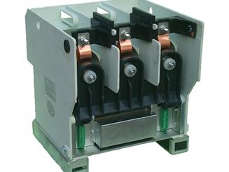
Compact medium voltage vacuum contactor, 12kV 400A.
Integrated molded frame structure of 12kv 400A vacuum contactor, compact design, saving your valued space of cabinet.
Read More

