


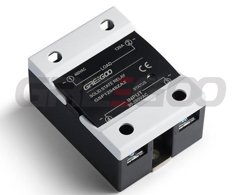
High voltage ac switching solid state relay
Home Products Solid State Relays (AC Switching)Single Phase Solid State RelaysHigh voltage ac switching solid state relay


Product Details
High voltage ac switching solid state relay
- Optical magnetic isolation between input and output circuits.
- Light Emitting Diode (LED) indicates working status.
- A set of normally open solid-state, contactless switch outputs, switching without sparks or arcing.
- The highest output withstand voltage in both forward and reverse directions is above 2400V.
- Epoxy resin encapsulated as a whole, shockproof and corrosion-resistant, stable and reliable operation. The product is mainly used for high voltage, high current, and high power load electrical equipment.
Specification
| Model | GH19Z | GH19R |
|---|---|---|
| Control Voltage | 5~32 VDC | 12-15VDC; 18-36VDC |
| Control Current | ≤25 mA | 160mA; 120mA |
| Start Current | ≥6 mA | 120mA; 80mA |
| Shut-off Voltage | ≤1.5 VDC | ≤10VDC; ≤12VDC |
| Switching Time | ≤10 mS | 0.8 mS |
| Load Voltage | 60~1200VAC | |
| Max Current | 60; 80; 100; 120; 150; 200A | |
| On-state Voltage Drop | ≤3.5 V | ≤8.5 V |
| Off-state Voltage | ≥2400V | |
| Turn-on Performance | Zero crossing switch on/off | Random control |
| Isolation Voltage | ≥2500 V | |
| Insulation Voltage | ≥2500 V | |
| Operating Temperature | -25~75 ℃ | |
| Power Frequency | 50/60 HZ | 1/800Hz |
| Cooling Conditions | Heat sink for 60A; Fan cooling for >100A | |
| Load Current Safety Factor | Resistive load 2-3 times, Inductive load 3-4 times | |
| Dimensions | 94×34×32 | 120×52×32 |
Notes while using
- When selecting a product, different current margins should be left according to the different nature of the load. (For resistive loads, select 2-3 times the load current. For inductive or capacitive loads, select 3-4 times the load current).
- Based on the relationship between load current and ambient temperature, when the ambient temperature is high or the heat dissipation conditions are poor, the current capacity should be increased and the size of the heat sink should be enlarged. To prevent load short circuits during use, it is required to connect a corresponding quick-break switch or fast fuse in series with the load circuit.
- For inductive (capacitive) loads, a varistor should be connected in parallel at the output end to prevent high voltages caused by high-order harmonics from damaging the solid-state switch. Selection of Metal Oxide Varistor (MOV): choose 1200-1500V for the 660V range. An AC overvoltage protection absorber produced by our factory can also be equipped.
- During installation, it is required that the contact surface between the heat sink and this product must be flat and smooth, and a layer of thermal conductive silicone grease should be applied to its surface. Finally, screws fitted with flat washers and spring washers should be symmetrically tightened and secured.
Inquiry
Need more information?
Contact us to request pricing, availability and customization options.
Related Products
Solid state relays
10A to 100A, single phase, three phase, dc to ac, dc to dc, ac to ac SSR.
View More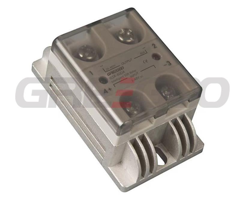
ISSR-40DA 60DA 25DA 40AA 25AA 60AA Intelligent SSR Relay
15A to 60A, ultra compact size, sensing the working status of the external environment
View More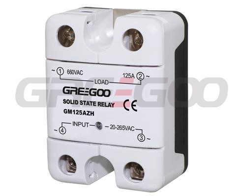
Integrated IP20 touch-safe removable covers Solid State Relays
660VAC
View More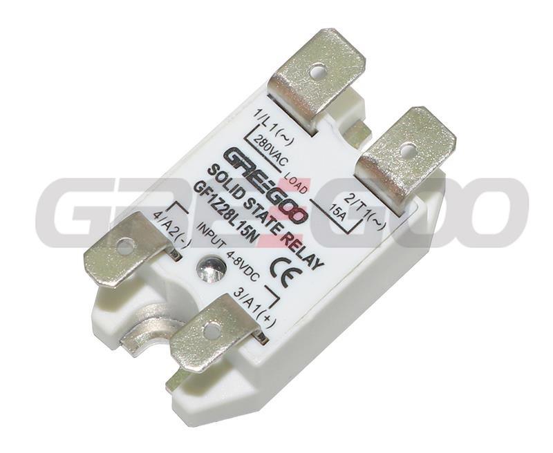
Compact FASTON terminals ac switching solid state relay
1-Phase, 15A and 25A, 230VAC, FASTON terminals connect
View More

