


What is the main difference between 8/20μs and 10/350μs in SPD?
The terms "8/20μs" and "10/350μs" refer to different surge waveforms used to characterize the performance and capability of Surge Protective Devices (SPDs). The numbers represent the time duration (in microseconds) of the surge current waveform and the surge voltage waveform, respectively. The main difference between these waveforms lies in their specific applications and the types of surges they simulate.
8/20μs Surge Waveform:
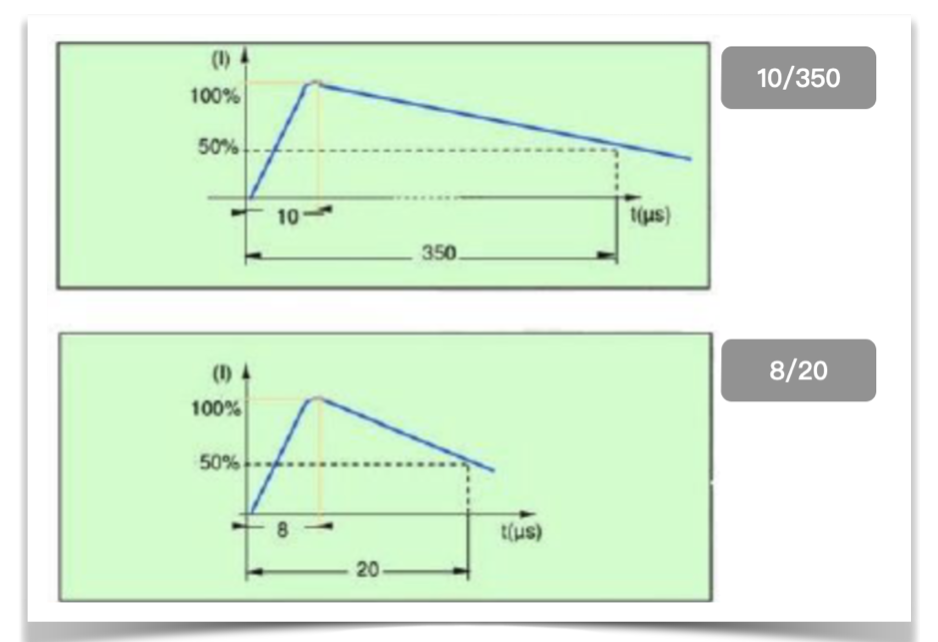
- The "8/20μs" waveform represents a surge current with a rise time of 8 microseconds and a decay time of 20 microseconds.
- This waveform is commonly used to simulate fast-rising and short-duration surges, such as those generated by lightning strikes or switching events in the power grid.
- SPDs rated with the 8/20μs waveform are suitable for protection against transient surges caused by lightning strikes and other rapidly occurring events.
10/350μs Surge Waveform:
- The "10/350μs" waveform represents a surge voltage with a rise time of 10 microseconds and a decay time of 350 microseconds.
- This waveform is used to simulate slower-rising and longer-duration surges, often associated with power distribution network switching operations and disturbances.
- SPDs rated with the 10/350μs waveform are appropriate for protection against sustained, longer-duration surges typically found in industrial settings and electrical distribution systems.
In summary, the main difference between 8/20μs and 10/350μs in SPDs lies in the type of surges they simulate and the application scenarios they are designed to protect against:
- 8/20μs: Suitable for protection against fast-rising and short-duration surges, such as lightning strikes and rapid switching events.
- 10/350μs: Suitable for protection against slower-rising and longer-duration surges, often associated with power distribution network switching operations and industrial electrical systems.
When selecting an SPD, it's essential to consider the specific application and the type of surges commonly encountered in the electrical system to ensure the appropriate level of protection for connected devices and equipment.

SOT 227 Package
FRED Diodes, Schottky Diodes, Thyristor Diode Module (MCD…io8/…io6),Rectifier Diode (DSI 2x…), Single Thyristor Module (MCO…)
Read More
How to use DC Current Shunt? A Comprehensive Guide on DC Shunt Resistor
Understanding DC Current Shunts, A Comprehensive Guide.
Read More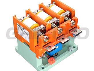
Greegoo's Vacuum Contactors Features and Benefits
Vacuum contactors are electrical devices with high performance, high safety, and high energy efficiency, suitable for various industrial and commercial applications.
Read More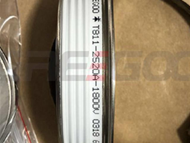
Fast thyristor, fast turn-on and high di/dt, lower switching losses.
Disc type Fast Switching Thyristors are popular used on metal smelting areas, induction heating furnace, smelting furnace, ARC furnace, Vacuum furnace, thyristor frequency converter.
Read More

