


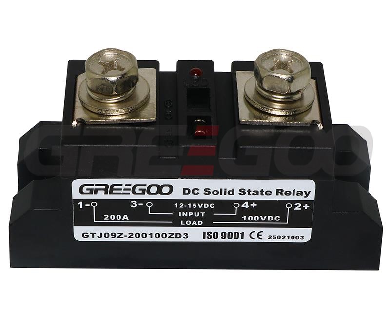
Low-voltage drop DC solid-state relay
Home Products DC to DC Solid State RelayCustom-made DC SSRLow-voltage drop DC solid-state relay


Product Details
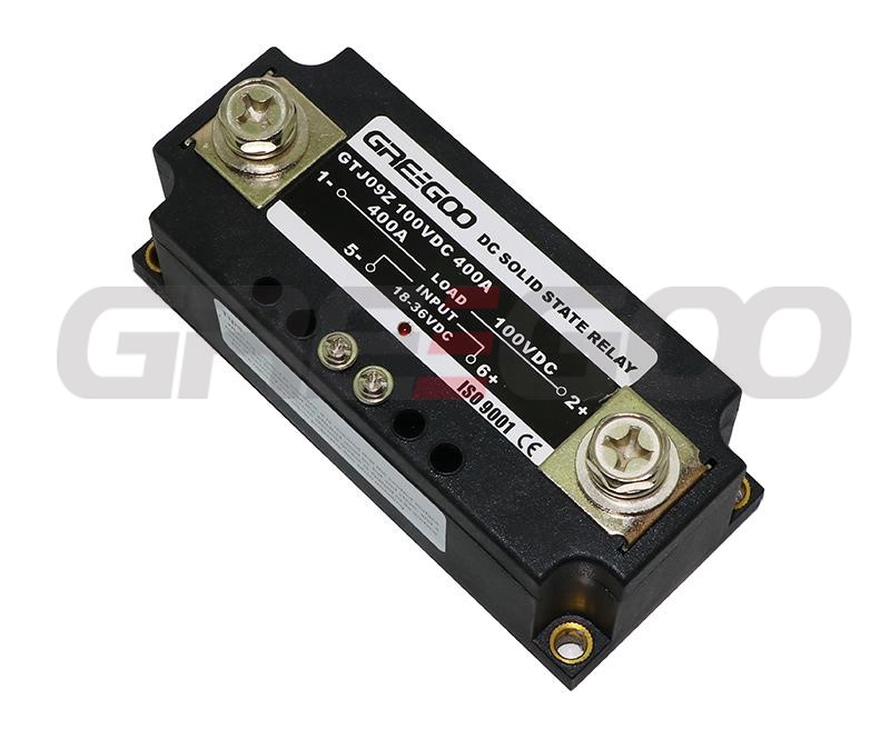
Low-voltage drop DC solid-state relay
Feature:
- There is optical isolation or transformer isolation between the input and output circuits.
- Control signal with TTL logic interface.
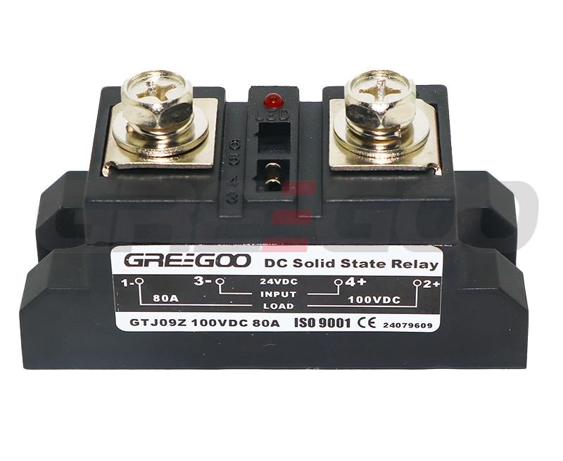
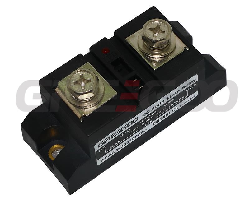
- LED indicator shows the operating status.
- Uses low-voltage drop solid-state devices, low power consumption, no need for heat dissipation with a heat sink.
- Integrated epoxy resin encapsulation, corrosion-resistant and shockproof, reliable operation.
- Mainly used for low-voltage, high-power DC electrical equipment that operates without the need for additional heat sinks, such as LED power switches, battery charging and discharging switches, low-voltage electric heaters switches, etc.
Specification
| Parameter | Value or Description |
|---|---|
| Model | GTJ09 (standard) GTJ09Z (100% load current protection) GTJ09L (50% load current protection) |
| Power Supply Control | 12~24 VDC / 50mA (optional for fast switching and lower power of control signal) |
| Control Voltage and Current | 12-15VDC 30-80mA; 18-36VDC 25-70mA |
| Operating Indicator | LED |
| Switching Time | ≤0.18 mS |
| Output Voltage | 60, 100, 200 VDC |
| Load Current | 30, 60, 80, 100, 120, 150, 200, 400A, 600A, 800A |
| On-state Voltage Drop | ≤0.01~0.5 V |
| Off-state Voltage | ≥60, 100, 200 VDC |
| Isolation Voltage | ≥1500 V |
| Insulation Voltage | ≥1500 V |
| Operating Temperature | -30 to 75 ℃ |
| Heat Dissipation Requirement | No additional heat sink required |
| Load Current Safety Factor | For resistive load, take 2.5-3 times the load current; for inductive load, take 3-5 times the load current |
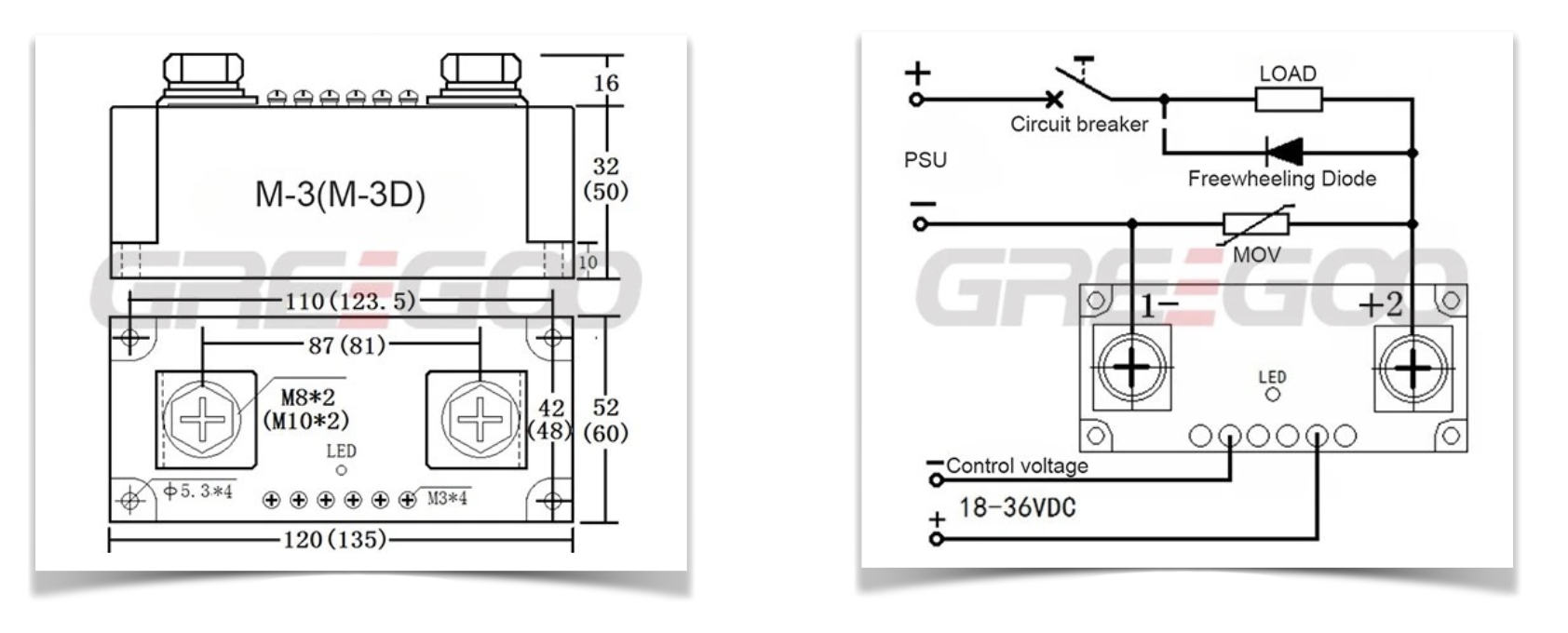
Diagram & Dimension

Notes while using
- Since the maximum output voltage value in the parameter table is equal to the forward blocking voltage value, a sufficient margin should be allowed when selecting. For resistive loads: it should be selected at 2 to 3 times the load voltage. For inductive loads: it should be selected at 3 to 4 times the load voltage.
- Current selection: For resistive loads, select at 1:1.5 to 2 times the actual current. For inductive loads, select at 1:2 to 4 times.
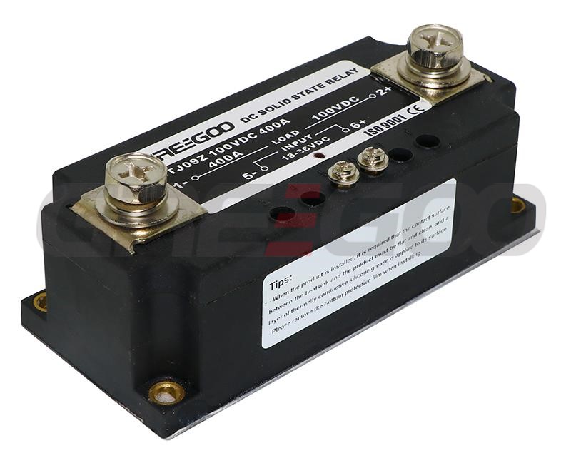
- Although the product does not require a heat sink for cooling during use, it is best installed on a metal base plate or a small-volume heat sink to dissipate the minimal amount of heat from the base plate.
- To prevent load short-circuiting and damage to the solid-state relay, it is required to connect a fast-acting circuit breaker slightly smaller than this product in series with the load circuit, or GTJ09L overcurrent protection type solid-state relay can be chosen.
- When the load is ready to run, the control power supply must be connected first, and then the control signal can be turned on or off. Do not connect the control signal first and then use the switching on and off of the control power supply.
- For inductive loads, a freewheeling diode must be connected in parallel across the load, or a varistor can be connected in parallel at the output (which can be selected at 1 to 1.5 times the power supply voltage) to prevent back voltage damage to the output tube when switching.
Inquiry
Need more information?
Contact us to request pricing, availability and customization options.


