Heatsink is not required single phase solid state relay
Home Products Solid State Relays (AC Switching)Special purpose SSR relaysHeatsink is not required single phase solid state relay


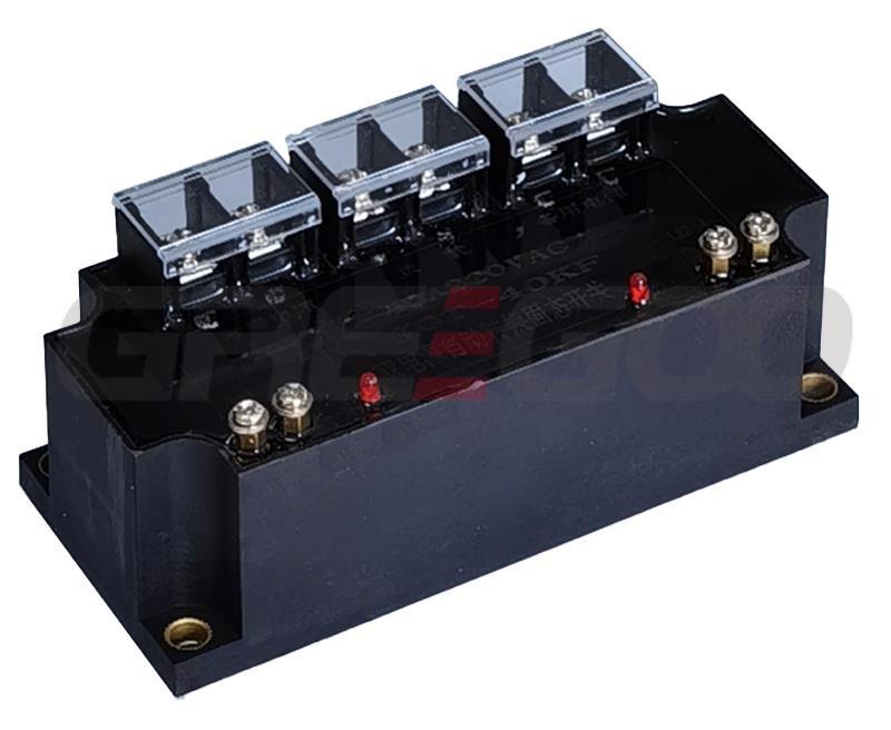
Heatsink is not required single phase solid state relay
- Optical isolation between input and output circuits.
- Tri-color LEDs indicate the switch program respectively.
- Solid-state, contactless switch performs zero-crossing turn-on and turn-off instantaneously, with automatic arc extinguishing.
- With contacts, it maintains a continuous on-state with low power consumption, minimal heating, and no need for cooling measures such as radiators or fans during use.
- Extremely compact in size, installation is extremely simple and can directly replace ordinary contactors.
- The product is mainly used for high-power electric heating devices, lighting devices, reactive power compensation devices, electrical switching devices, etc., that have a low switching frequency, long continuous operation time, high working environment temperature, and poor ventilation facilities.
| Model | GT11 | GT12 |
|---|---|---|
| Load Voltage | 240V, 440V, 660V | |
| Maximum Load Current | 40~200A | 40~120A |
| On-State Voltage | ≤0.15 V | ≤0.15 V |
| Control Voltage | 12 VDC | 220 VAC |
| Control Current | ≤300 mA | ≤150 mA |
| On/Off Time | ≤10 mS / ≤500 mS | ≤10 mS / ≤500 mS |
| Off-State Voltage | 900V, 1200V, 1600V | |
| Isolation Voltage | ≥2000 V | |
| Insulation Voltage | ≥2000 V | |
| Insulation Resistance | ≥100 MΩ | |
| Power Frequency | 50~60 HZ | |
| Operating Temperature | -20~75 ℃ | |
| Load Current Safety Factor | Resistive load: 2.5-3 times, Inductive/Capacitive load: 3-5 times | |
| Dimensions | 94×34×71 mm | |
- There is optical isolation between the input and output circuits.
- The solid-state contactless switch executes zero-crossing turn-on and turn-off, extinguishing the arc automatically.
- When contacts are in a continuous on state, power consumption is low, and there is minimal heat generation; thus, there is no need for cooling measures such as heatsinks or fans during use.
- The control power line and signal line are integrated; the two wires can control the main switch.
- When the product is in operation, the maintenance current is very small, with power consumption close to zero.
- The product is mainly used as a switching switch in capacitive loads, such as reactive power compensation equipment.
| Model | GT11A |
|---|---|
| Load Voltage | 240V, 440V, 660V |
| Maximum Load Current | 60~150A |
| On-State Voltage | ≤0.1 V |
| Control Voltage | 12-15 VDC |
| Control Current | Static working current: A≤10mA; Switch transient current: ≤0.3A; On/Off pulse width: ≥0.5S |
| On/Off Time | ≤10 mS / ≤0.3 S |
| Off-State Voltage | 900V, 1200V, 1600V |
| Isolation Voltage | ≥2000 V |
| Insulation Voltage | ≥2000 V |
| Insulation Resistance | ≥100 MΩ |
| Power Frequency | 50~60 HZ |
| Operating Temperature | -20~75 ℃ |
| Load Current Safety Factor | Resistive load: 2.5-3 times, Inductive (Capacitive) load: 3-5 times |
| Dimensions | 94×34×71 mm |
-
When selecting products, different allowances should be considered for current and voltage grades based on the nature of the load. Overcurrent protection measures should also be added to the load circuit to prevent short-circuiting. This can be achieved by connecting a fast-acting fuse or an air switch in series with the load circuit.
-
When dealing with inductive loads, overvoltage protection measures should be added to the output end to prevent the thyristor from overvoltage breakdown. This can be done by paralleling a varistor (MOV) or a resistor-capacitor (R.C) snubber circuit across the output. The selection of MOV: for a 220V power supply, choose between 430-470V; for a 380V power supply, select between 1100~1200V.
-
For the GT11 type solid-state relay, the control voltage should not be less than 10VDC; otherwise, due to loss of control inside the solid-state relay, the thyristor may overheat and cause permanent damage.
-
Since this model of solid-state relay uses a composite material structure at the output end, its working frequency is relatively low. If it is to work for extended periods at high switching frequencies, an additional heatsink should be installed for cooling.
-
When the solid-state relay is functioning normally in switching operations, the indicator light should change through yellow-red-green colors (when turning on, it should go from yellow to red; when turning off, from green to off). If the colors do not change according to this sequence, immediately cut off the power to the output end and check whether the control program of the solid-state relay is functioning properly.
- When selecting products, it is necessary to leave different margins for current and voltage ratings based on the nature of the load. For example, when dealing with capacitive loads, the current specification chosen should be 2.5 to 5 times greater than the actual current.
- To prevent overcurrent or short-circuiting of the load, overcurrent protection measures should be added to the main circuit. This can be done by connecting a fast-acting circuit breaker or fast-acting fuse in series with the load circuit.
- For inductive or capacitive loads, overvoltage absorption protection measures should be added to the output end to prevent the thyristor from overvoltage breakdown. This can be achieved by paralleling a varistor (MOV) and a snubber circuit (R, C) across the output. The selection of MOV: for a 440V category, choose between 680-720V; for a 660V category, select between 1100~1200V. Alternatively, use an AC overvoltage protection absorber produced by our factory.
- The control voltage must not be less than 11VDC; otherwise, the solid-state relay may lose control internally, causing the thyristor to overheat and result in permanent damage.
- For composite solid-state relays, since the output end uses a composite material structure, the working frequency is relatively low. If it is to operate for extended periods at high switching frequencies, additional cooling with a heatsink should be applied.
Need more information?
Contact us to request pricing, availability and customization options.