


Solid state Relay with Load Circuit Monitoring
Home Products Solid State Relays (AC Switching)Single Phase Solid State RelaysSolid state Relay with Load Circuit Monitoring
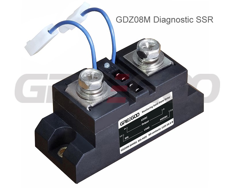
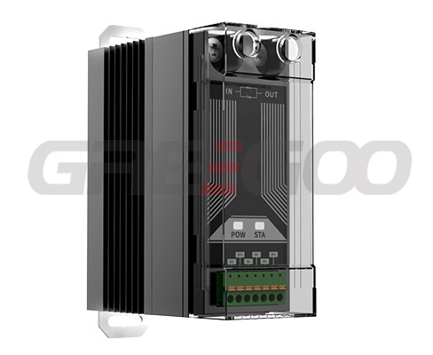
Solid state Relay with Load Circuit Monitoring
- Optoelectronic isolation between input and output with insulation voltage ≥2500V and isolation voltage ≥2000V.
- Control interface compatible with TTL and PLC logic signals.
- Dual-color LED indicators to distinguish normal operation and fault status.
- Contactless solid-state output enables fast switching with no electric arcing or sparks.
- Fully encapsulated construction with waterproof, anti-corrosion and shock resistance. Built-in automatic over-temperature protection for long service life and easy installation.
Input (Control Side) Parameters
- Control power supply: 12VDC (0.3W) / 24VDC (0.7W)
- Control signal: 4–32 VDC
- Maximum control current: ≤28 mA
- Indicator light definition: Green light = normal operation; Red light = damaged SSR or abnormal/open load
- Switching response time: ≥10 mS
Output (Load Side) Parameters
- Load voltage: 24–240 VAC or 44–440 VAC
- Optional rated load currents: 60, 80, 90, 100, 120, 150, 200, 300, 400, 500 A
- On-state voltage drop: ≤1.4–1.8 V
- Off-state withstand voltage: ≥800V or ≥1500V
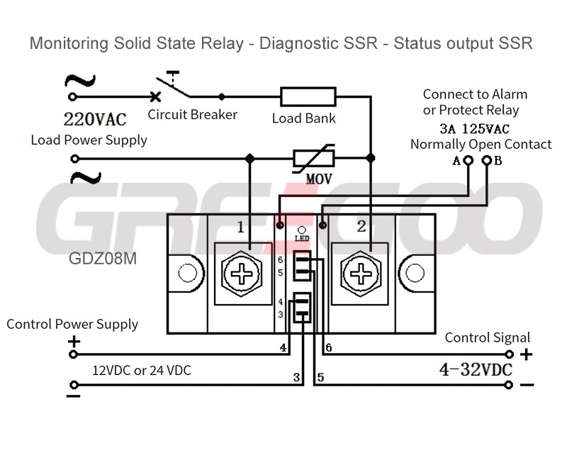
- Fault alarm auxiliary contacts: 3A 125VAC. Normally open under normal conditions, closed upon fault; can be connected to external alarms or protective relays.
General Performance Parameters
- Electrical isolation: Isolation voltage ≥2000V; insulation voltage ≥2500V
- Operating temperature range: -30 ℃ ~ 90 ℃
- Compatible power frequency: 50/60 Hz
- Heat dissipation requirements: Heat sink mandatory for current ≥60A; forced air cooling fan required for current ≥120A.
- Current safety margin for selection: 2–3 times rated load current for resistive loads; 3–5 times for inductive/capacitive loads
Steady green light: The relay and load work normally; Steady red light: SSR damaged or load open circuit; Alternating flickering red & green lights: Hidden malfunctions, machine shutdown and inspection required.
Before applying the control signal, if the red light is on and the auxiliary contacts (points A and B) change from normally open to normally closed, check whether the circuit heater is open or the solid-state relay is damaged. When the green light is on, the circuit is fully operational, and the control signal can be applied to start the device. If flickering of the red and green lights is observed during operation (while applying pulse-width modulated signals), it indicates an abnormality, and the device must be stopped for inspection.
· When selecting a product, appropriate current derating should be applied based on the nature of the load. (For resistive loads: 2-3 times the load current. For inductive or capacitive loads: 3-4 times the load current.)
· To prevent damage to the solid-state switch due to load short circuits, connect a fast-acting circuit breaker, fast-blow fuse, or select the SSR with over-current protection, matching the load current rating.
· For inductive loads, connect a varistor across the output terminals to protect against transient high voltages that could damage internal components.
· If intermittent load connection is observed during use, it may be caused by overheating protection due to poor heat dissipation of the solid-state switch. Check for loose mounting screws, fan failure, or insufficient heat sink size.
· During installation, ensure that the contact surface between the heat sink and the product is flat and smooth. Apply a layer of thermal grease, and securely fasten the screws with flat washers and spring washers using a symmetrical tightening method.
Need more information?
Contact us to request pricing, availability and customization options.
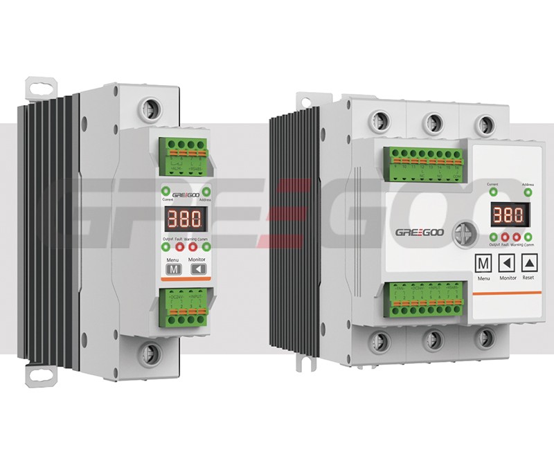
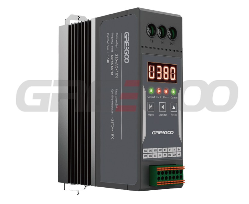
Intelligent Solid State Relay - Diagnostic SSR - Communication SSR
Current digital display, MODBUS communication, RS485 port, Temperature detection, Phase loss detection, Panel function LEDs for operational status monitoring etc.
SCR regulator single phase super slim type
Super slim type 20A/40A 100V-380VAC
Solid state relay with diagnostic
40A 220V built-in RC snubber circuit, diagnostic over temperature and load open-circuit