


Solid State Automatic Transfer Switch
Home Products Solid State Relays (AC Switching)Multi-output solid state relaysSolid State Automatic Transfer Switch
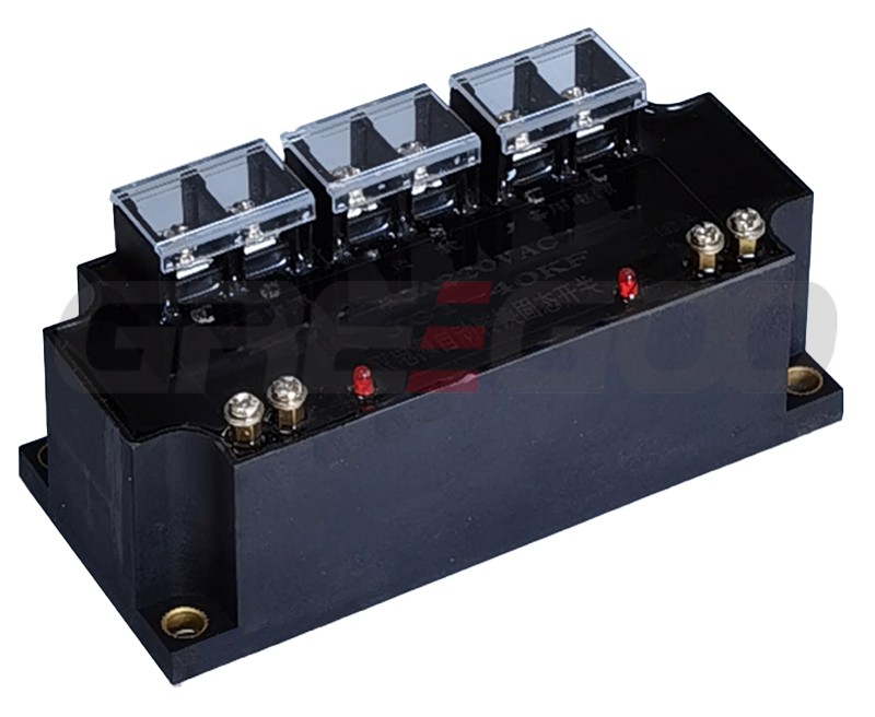
Solid State Automatic Transfer Switch
Features
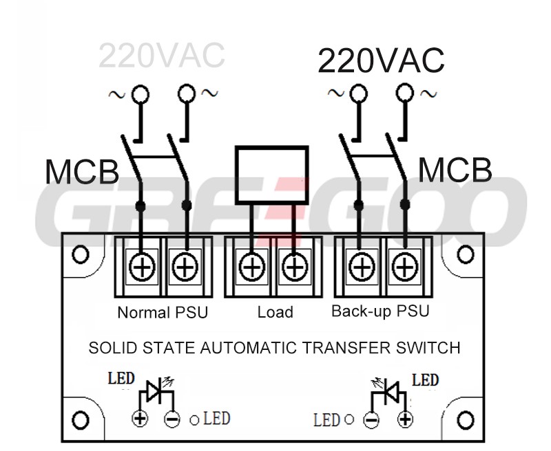
The automatic power source switching can be performed without the need for additional control signals.
The switch used is a two normally open, two normally closed - contactless solid-state switch.
There is no sound, no sparks, and no arcing during switch on/off operations.
The power source switching is fast, with a maximum switching time of less than 20ms.
It is encapsulated in epoxy resin, providing shock resistance, moisture protection, and stable, reliable operation.
The external structure is simple, and the installation and wiring are easy, with no need to distinguish between neutral and live wires.
The product is mainly used for automatic switching of uninterruptible power supplies (UPS) for computers, instruments, and other equipment.
|
Specification |
Value |
|
Model |
SATS-20/240 SATS-40/240 SATS-60/240 SATS-80/240 SATS-100/240 |
|
Load Power Supply |
110~240VAC |
|
Maximum Load Current |
20A, 40A, 60A, 80A, 100A |
|
On-state Voltage Drop |
≤ 4.0V |
|
Off-state Voltage |
≥ 800V |
|
Switching Time |
≤ 20ms |
|
Power Indicator |
Main Power: Red LED, Backup Power: Green LED |
|
Switching Characteristics |
Contactless solid-state switch, automatic switching |
|
Isolation Voltage |
≥ 1500V |
|
Insulation Voltage |
≥ 2000V |
|
Operating Temperature |
-25°C ~ 75°C |
|
Power Frequency |
50/60Hz |
|
Heat Dissipation |
≥10A with heat sink, ≥60A with fan cooling |
|
Load Current Safety Factor |
Resistive load: 2-3 times, Inductive load: 3-4 times |
|
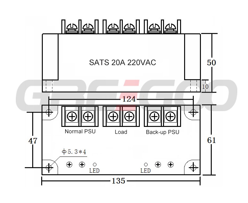
Dimensions |
135×61×50 mm |
Additional Guidelines for Load and Installation
Margin Based on Load Type:
For resistive loads, select a current rating 2-3 times the load current.
For inductive or capacitive loads, select a current rating 3-4 times the load current.
Current Capacity Based on Environmental Temperature:
When the ambient temperature is high or the cooling conditions are poor, increase the current capacity.
Protection Against Short Circuit:
To prevent short circuits when using the load, a fast disconnect switch, quick fuse, or an overcurrent/short circuit protection solid-state switch from the SATS...-L series should be used in the load circuit.
For Inductive Loads:
A voltage-sensitive resistor (MOV) should be connected at the output to prevent internal damage to the solid-state chip from overvoltage conditions.
MOV Selection: For the 240V range, use a 430-470V MOV, or choose an overvoltage protection absorber produced by the manufacturer.
Installation Requirements:
Ensure that the contact surface between the heat sink and the product is flat and smooth.
Apply a layer of thermal conductive silicone grease on the surface of the heat sink.
Finally, tighten the screws symmetrically, after adding flat washers and spring washers, to secure the assembly.
Need more information?
Contact us to request pricing, availability and customization options.
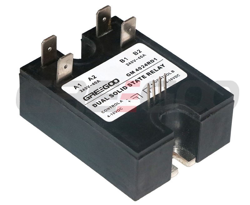
Dual solid state relays
Dual output SSR, SCR output, 10A to 80A, single phase.
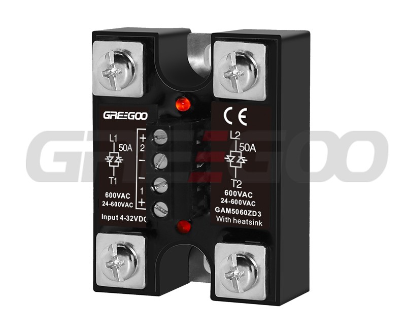
2 phase output solid state relays
2 phase SSR, 25A, 40A, 50A, 40-480 or 600Vac output, 4-32Vdc control, zero crossing and random control.
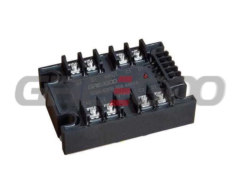
4 channel output Solid State Relay
4 output Solid State Relays, 240V/440V/660VAC up to 100A.
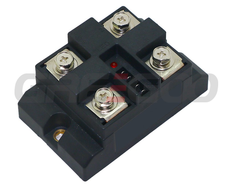
2 pole AC switching solid state relays
Dual output, ac switching, dual control and dual output, one control dual output optional.