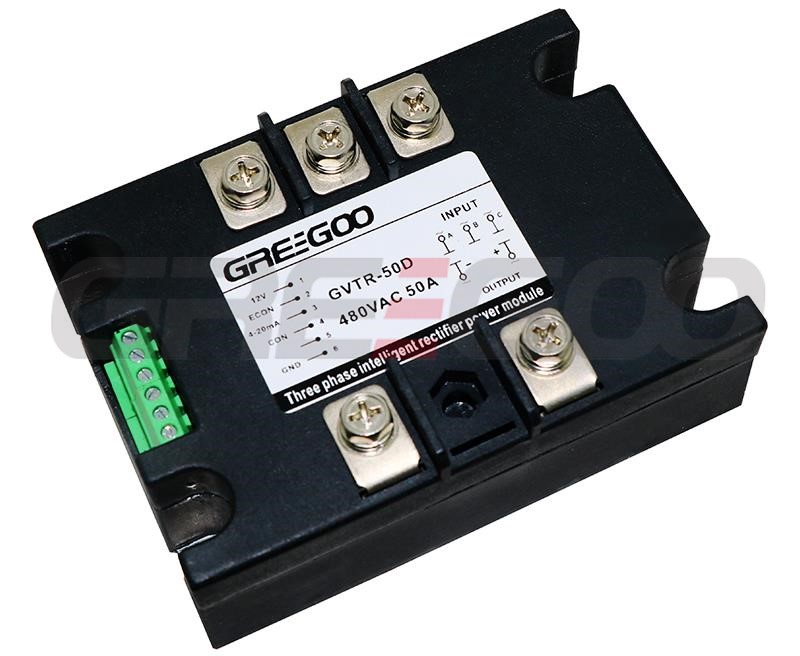
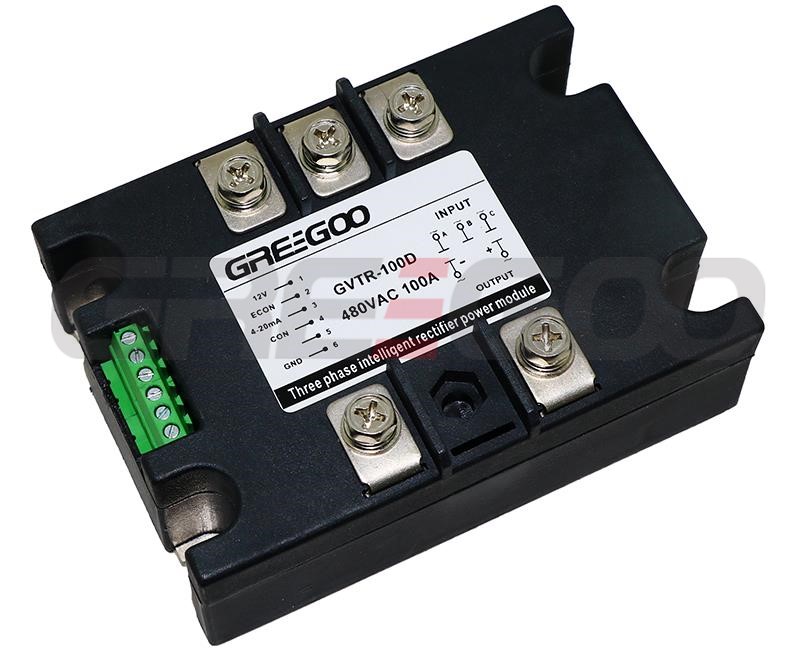
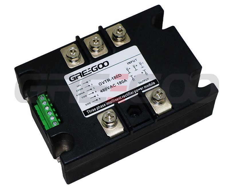
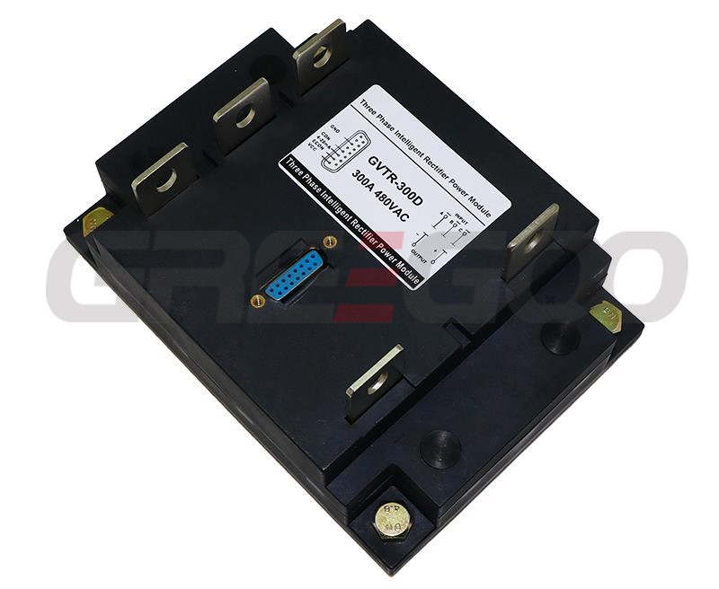
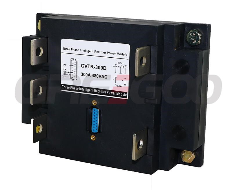
GVTR/GVDR series 3 and single phase rectifier IPM modules
Home Products SCR Power ControllerIntelligent Power Modules (IPM module)GVTR/GVDR series 3 and single phase rectifier IPM modules
GVTR/GVDR series 3 and single phase rectifier IPM modules
| Rated Current |
Single Phase | Three Phase |
| 480VAC | 480VAC | |
| 50A | GVDR-50D | GVTR-50D |
| 70A | GVDR-70D | GVTR-70D |
| 100A | GVDR-100D | GVTR-100D |
| 120A | GVDR-120D | GVTR-120D |
| 150A | GVDR-150D | GVTR-150D |
| 200A | GVDR-200D | GVTR-200D |
| 250A | GVDR-250D | GVTR-250D |
| 350A | GVDR-350D | GVTR-350D |
| 500A | GVDR-500D | GVTR-500D |
| 800A | GVDR-800D | GVTR-800D |
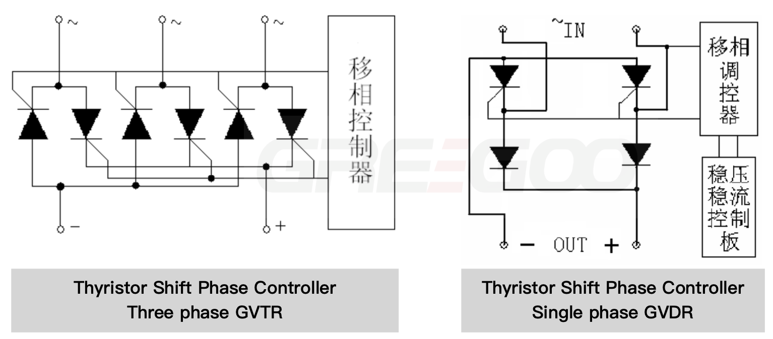
Single-phase Rectifier Voltage Regulation Module is a multifunctional power integrated module that encapsulates a thyristor power circuit, a microcontroller-controlled phase-shift trigger circuit, a signal detection sensor circuit, and a voltage regulation circuit. It can achieve precise control of the load voltage, featuring a built-in linear control circuit with high accuracy and good stability. The rated current ranges from 50 to 500A, and the rated voltage is 220V or 380V. It is widely used in various inductive and resistive loads, such as DC motors, electrolysis, temperature control, dimming, and DC voltage regulation.
| Function | Single-phase AC Thyristor Rectification |
|---|---|
| Input Voltage Range | 220V±20% / 380V±20% |
| Output Waveform Asymmetry | ≤2% |
| Control Signal Voltage | 0-10VDC (Input Impedance 10KΩ) |
| Control Current | 4-20mA (Input Impedance 330Ω) |
| Manual Potentiometer Resistance | 10KΩ |
| Cooling Method | Heat sink air cooling, air speed ≥6m/s |
| Operating Temperature | -30 ~ 40℃ |
| Storage Temperature Range | -25 ~ 55℃ |
| Main Circuit Electrical Parameters | Unit | Parameter Values |
|---|---|---|
| Nominal Current | Arms | 50, 70, 100, 120, 200, 250, 350, 500 |
| Thyristor Blocking Voltage | Vpk | 800—1200 |
| Off-state Leakage Current (Max.) | mArms | ≤8, ≤10, ≤10, ≤10, ≤10, ≤15, ≤15, ≤20 |
| On-state Voltage Drop (Max.) | Vrms | 1.6, 1.6, 1.6, 1.8, 1.8, 1.8, 1.8, 1.8 |
| Insulation Voltage (Terminal/Baseplate) | Vrms | ≥2500 |
| Weight | Kg | 0.425, 2.2 |
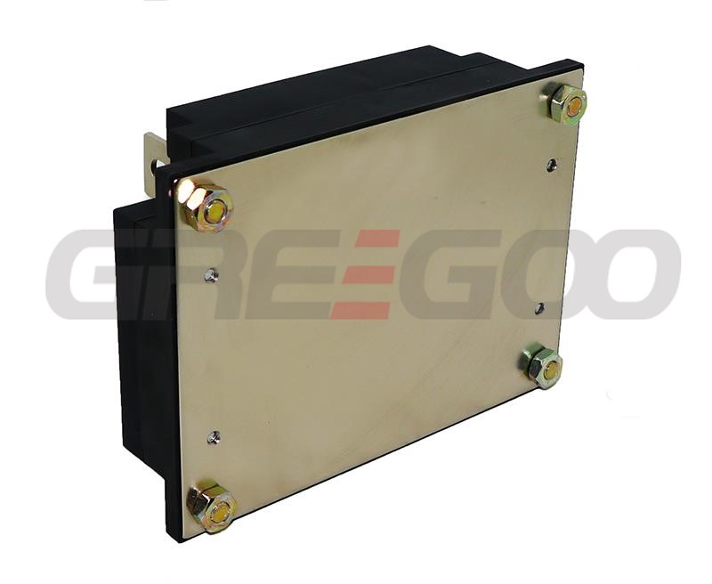
Three-phase Rectifier Phase-shift Voltage Regulation Module is a multifunctional power integrated module that encapsulates a three-phase thyristor main circuit and a phase-shift trigger control circuit. It is a complete power phase-shift open-loop control system that can achieve rectification and voltage regulation of three-phase power. The product is widely used in DC motor speed control, industrial automation, electric heating control, mechatronics, various power supplies, chemical, textile communications, and other fields. It can achieve manual and automatic control interfaces, with no phase sequence requirement for the main circuit AC input, and features a linear control circuit with high accuracy and good stability.
| Input voltage | 220V or 380V ±20% |
| Power source | 12V,≤400mA |
| Controlling voltage | 0-10VDC |
| Controlling current | 4-20mA |
| Hand-control potentiometer resistance | 10KΩ |
| Colling method | Wind-colling radiator,wind speed≤6m/s |
| Ambient temperature | -30~ 40℃ |
| Output voltage | 0-513VDC |
| Parameter | Unit | Value | ||||||||
| Load current | Arms | 50 | 70 | 120 | 200 | 250 | 350 | 500 | 800 | |
| Max working current | Arms | 3x50 | 3x70 | 3x120 | 3x200 | 3x250 | 3x350 | 3x500 | 3x800 | |
| TRIAC over voltage | Vpk | 1200 | ||||||||
| Frequency | Hz | 50/60 | ||||||||
| Off state voltage rising rate | V/sec | 500 | ||||||||
| On state voltage rising rate | A/sec | 100 | ||||||||
| Off state leakape current | mArms | ≤8 | ≤10 | ≤10 | ≤10 | ≤15 | ≤15 | ≤20 | ≤20 | |
| On state leakape current | Vrms | 1.6 | 1.6 | 1.8 | 1.8 | 1.8 | 1.8 | 1.8 | 1.8 | |
| Voltage drop insulating voltage | Vrms | ≥2500 | ||||||||
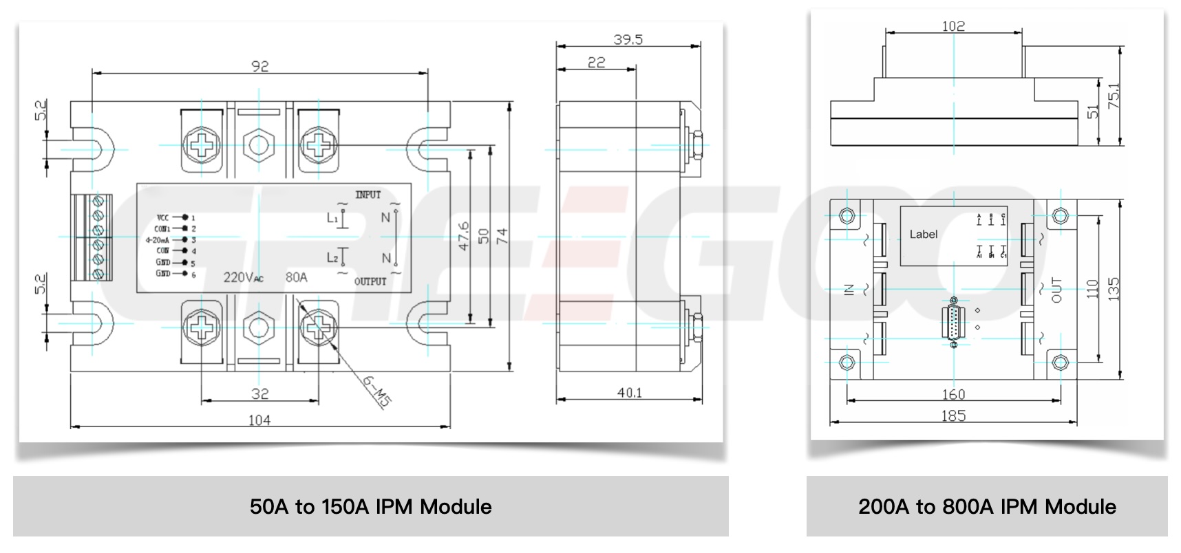

- For the 220V module, the input and output neutral and live wires must not be reversed. Connect L1 to the live wire, L2 to the load, and N to the neutral wire, as labeled in Figure 1. For 380V and 440V modules, L1 and L2 can be connected arbitrarily.
- The red LED indicates a 12V power supply, and the green LED indicates operation. When using, first connect the 12V control power supply. At this time, the red LED will be on, and the green LED will be off. Then connect the AC main circuit. After a 1-second self-check by the microcontroller, the green LED will light up, indicating normal operation. Please use a 12V/1A switching power supply.
- This module uses a positive control method, meaning when the input control voltage (current) is 0V (or 4mA), the AC output is 0V. When the input control voltage is 10V (or 20mA), the AC output is approximately equal to the AC power supply voltage.
- The 200A—500A voltage regulation module terminals use a 232 socket wiring method. The ports are VCC (red), CON1 (orange), CON (yellow), 4-20mA (green), and GND (black). Other ports are empty pins. As shown in the diagram, the connection method is the same as in Figure 5.

-
The diagram below shows the control output curves for inductive and resistive loads as measured on the module, provided for user reference.

Need more information?
Contact us to request pricing, availability and customization options.

Thyristor Power Controller (single phase)
40A to 200A 220V/380VAC
View More
Single phase rectifier intelligent power module
30A to 400A, 0-198VDC or 0-342VDC.
View More
Constant Voltage or Constant Current IPM Modules
Constant voltage, 150A to 1000A.
View More
Three Phase Thyristor Voltage Regulator
10A to 200A 0-380VAC
View More


