GVTA/GVDA Three and Single Phase AC Switching IPM Modules
Home Products SCR Power ControllerIntelligent Power Modules (IPM module)GVTA/GVDA Three and Single Phase AC Switching IPM Modules
GVTA/GVDA Three and Single Phase AC Switching IPM Modules
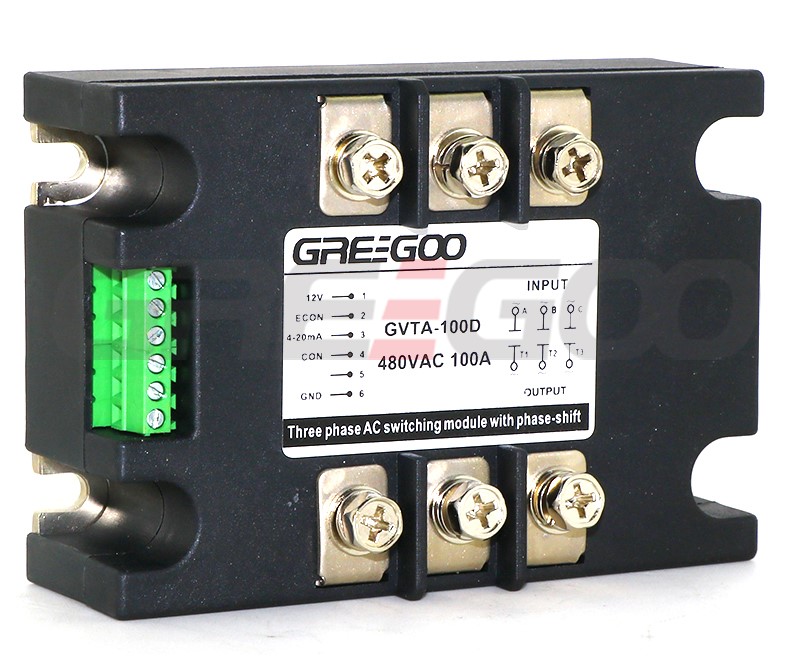
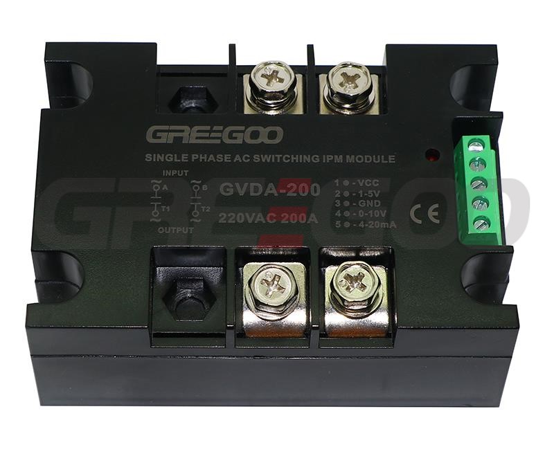
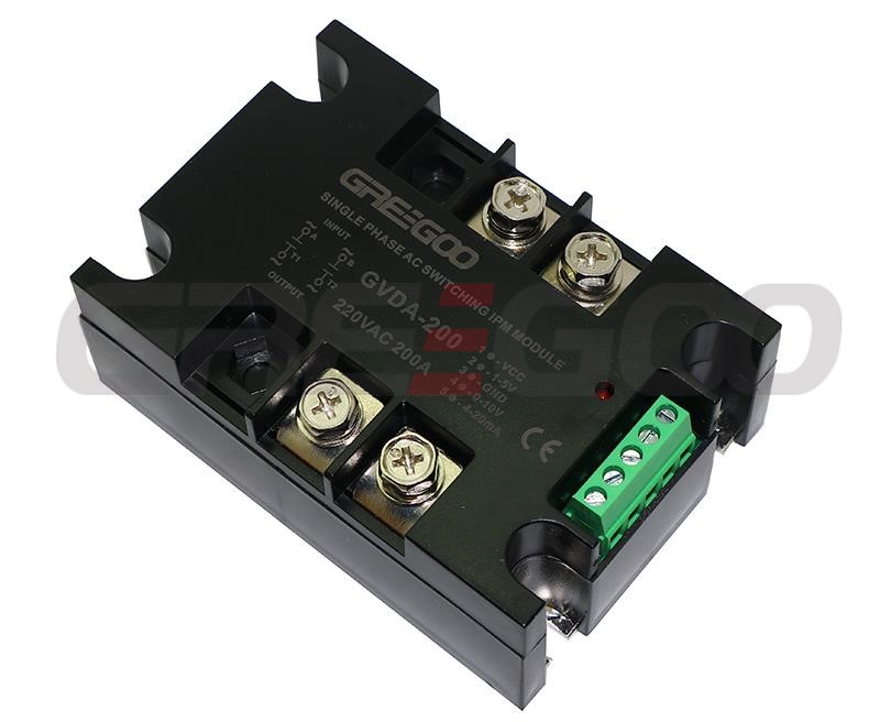
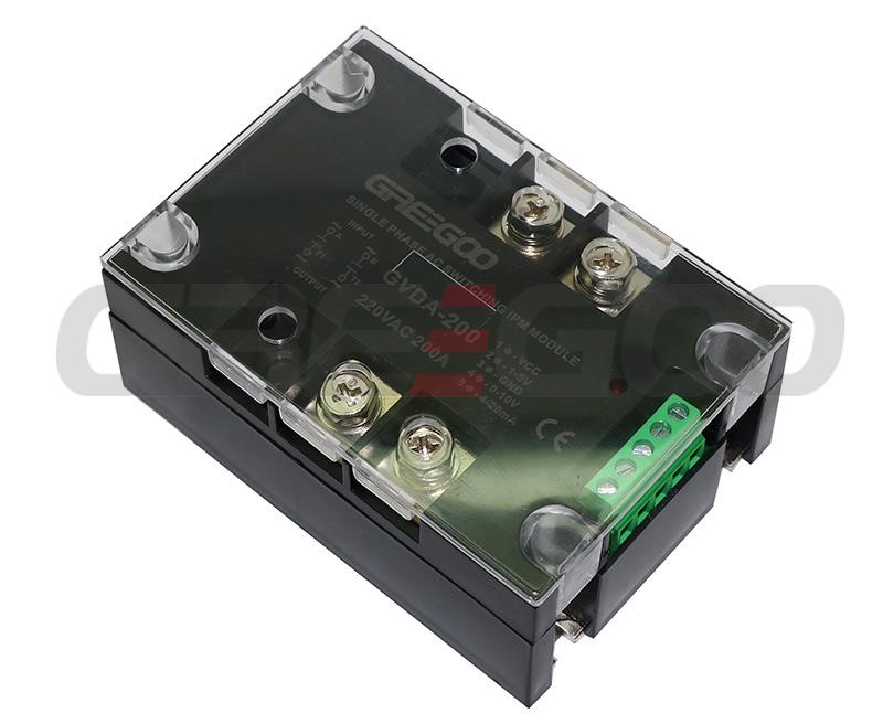
The single phase and three phase SCR power controller, also called AC voltage regulation module is an integrated power module designed for precise control of load voltage. It encapsulates a thyristor power circuit, a microcontroller-controlled phase-shift trigger circuit, a signal detection sensor circuit, and a voltage regulation circuit. With a built-in linear control circuit, it offers high precision and stability. The module supports a rated current range of 50A to 800A, rated voltages of 220V, 380V, and 440V, and frequencies of 50Hz and 60Hz. It is widely used in applications requiring precise voltage regulation, such as various inductive and resistive loads, AC motor control, transformer regulation, temperature control, dimming, and AC voltage regulation, making it suitable for a variety of industrial and commercial equipment.
| Parameter | Unit | Value |
|---|---|---|
| Input Voltage Range | 220V±20%, 380V±20%, 440V±20% | |
| Output Waveform Asymmetry | ≤2%, ≤6% | |
| Control Signal Voltage | VDC | 0-10 (Input Impedance 10KΩ) |
| Control Current | mA | 4-20 (Input Impedance 330Ω) |
| Manual Potentiometer Resistance | KΩ | 10 |
| Cooling Method | Heat sink air cooling, wind speed ≥6m/s | |
| Operating Temperature | ℃ | -30 ~ 40 |
| Storage Temperature Range | ℃ | -25 ~ 55 |
| Rated Current | Arms | 50, 70, 100, 120, 150, 200, 250, 350, 500, 800 |
| Thyristor Blocking Voltage | Vpk | 800-1200 |
| Off-state Leakage Current (Max.) | mArms | ≤8, ≤10, ≤10, ≤10, ≤10, ≤10, ≤15, ≤15, ≤20,≤20 |
| On-state Voltage Drop (Max.) | Vrms | 1.6, 1.6, 1.6, 1.8, 1.8, 1.8,1.8, 1.8, 1.8,1.8 |
| Insulation Voltage (Terminal/Baseplate) | Vrms | ≥2500 |
| Weight | Kg | 0.425, 2.2 |
Note: Red mark parameter is for three phase only, the power supply is 12V, ≤400mA.
| Rated Current |
Single Phase | Three Phase | Single Phase | Three Phase |
| 480VAC 50Hz | 480VAC 50Hz | 480VAC 60Hz | 480VAC 60Hz | |
| 50A | GVDA-50D | GVTA-50D | GVDA-50E | GVTA-50E |
| 70A | GVDA-70D | GVTA-70D | GVDA-70E | GVTA-70E |
| 100A | GVDA-100D | GVTA-100D | GVDA-100E | GVTA-100E |
| 120A | GVDA-120D | GVTA-120D | GVDA-120E | GVTA-120E |
| 150A | GVDA-150D | GVTA-150D | GVDA-150E | GVTA-150E |
| 200A | GVDA-200D | GVTA-200D | GVDA-200E | GVTA-200E |
| 250A | GVDA-250D | GVTA-250D | GVDA-250E | GVTA-250E |
| 350A | GVDA-350D | GVTA-350D | GVDA-350E | GVTA-350E |
| 500A | GVDA-500D | GVTA-500D | GVDA-500E | GVTA-500E |
| 800A | GVDA-800D | GVTA-800D | GVDA-800E | GVTA-800E |

- For the 220V module, the input and output neutral and live wires must not be reversed. Connect L1 to the live wire, L2 to the load, and N to the neutral wire, as labeled in Figure 1. For 380V and 440V modules, L1 and L2 can be connected arbitrarily.
- The red LED indicates a 12V power supply, and the green LED indicates operation. When using, first connect the 12V control power supply. At this time, the red LED will be on, and the green LED will be off. Then connect the AC main circuit. After a 1-second self-check by the microcontroller, the green LED will light up, indicating normal operation. Please use a 12V/1A switching power supply.
- This module uses a positive control method, meaning when the input control voltage (current) is 0V (or 4mA), the AC output is 0V. When the input control voltage is 10V (or 20mA), the AC output is approximately equal to the AC power supply voltage.
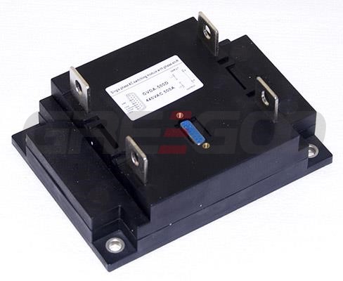
- The 200A—500A voltage regulation module terminals use a 232 socket wiring method. The ports are VCC (red), CON1 (orange), CON (yellow), 4-20mA (green), and GND (black). Other ports are empty pins. As shown in the diagram, the connection method is the same as in Figure 5.

-
The diagram below shows the control output curves for inductive and resistive loads as measured on the module, provided for user reference.


Need more information?
Contact us to request pricing, availability and customization options.

Three Phase Thyristor Voltage Regulator
10A to 200A 0-380VAC
View More
Single phase AC switching intelligent power module
20A to 1200A, 0-220VAC or 0-380Vac.
View More
Three phase rectifier IPM module
30A to 1000A 0-513VDC
View More
Constant Voltage or Constant Current IPM Modules
Constant voltage, 150A to 1000A.
View More


