36KV Vacuum Contactor (EVC9)
Home Products Vacuum ContactorHigh Voltage Vacuum Contactor (40.5KV)36KV Vacuum Contactor (EVC9)
36KV Vacuum Contactor (EVC9)
The EVC9 series AC high-voltage vacuum contactor (hereinafter referred to as "contactor") is suitable for AC power systems with a frequency of 50 to 60Hz and a rated voltage of 40.5KV in the main circuit. It is designed for power networks with rated currents ranging from 630A to 2000A, providing remote switching and breaking, as well as frequent starting and controlling of AC motors, transformers, capacitor banks, and similar applications.
- Ambient temperature: -25°C to 40°C.
- Installation location: The altitude does not exceed 2000m (customized for altitudes above 2000m).
- Relative humidity of the air: The monthly average maximum relative humidity during the wettest month is 90%, with a monthly average minimum temperature of 25°C. Consideration should be given to frost occurring on the product surface due to temperature changes.
- Environment: The contactor should be used in environments free from water intrusion, corrosive and flammable gases, and severe vibrations.
- Properly select the technical parameters of the contactor, ensuring that auxiliary switch contacts are not overloaded, and the contact capacity is 5A.
- Provide sufficient insulation space around and above the contactor to ensure safe usage.
- If there is no response when the control power is turned on, immediately disconnect the control power to check the cause, preventing damage to the electromagnetic coil.
- Strictly differentiate between AC and DC in the control circuit. The make, break, and common control terminals should have passive contacts, and long-term energized control is not allowed to prevent damage to the control circuit.
- During switch testing (make and break operations), to ensure the capacitor is fully charged, the interval time between make and break operations should not be less than 5 minutes.
- Contactors are not suitable for series and parallel operation.
- The main circuit connection principle is: the upper end (static end) is the incoming end, and the lower end (moving end) is the outgoing end.
- Product specifications are rated at a voltage of 40.5KV, with rated currents of 630A, 800A, 1250A, 1600A, and 2000A, respectively.
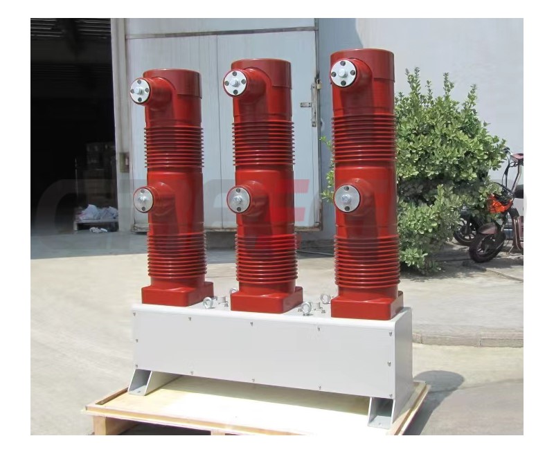
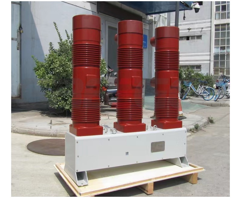
Structure: This series of contactors consists of an insulating cylinder, metal base shell, transmission system, permanent magnet mechanism, auxiliary switch, vacuum switch tube, etc. The structure features a high-voltage circuit and low-voltage control with a separate upper and lower structure. It is aesthetically pleasing, safe, reliable, and easy to install and maintain.
Operating Principle: This contactor completes the make-and-break operations by controlling the permanent magnet mechanism. After connecting the control power to the switch, the internal control system charges the make-and-break capacitors. To close the switch, a short-duration pulse signal is applied to the common (COM) and close (A) terminals (passive short circuit), and then the switch maintains the closed state through the permanent magnet mechanism. To open the switch, a short-duration pulse signal is applied to the common (COM) and open (B) terminals (passive short circuit), and then the switch maintains the open state through the permanent magnet mechanism. This permanent magnet mechanism is reliable, energy-efficient, and suitable for long-duration closing in electrical applications, especially for controlling electrical equipment such as power supply transformers.
Technical Parameters
Secondary Circuit Schematic:Permanent magnet type
Heating Current for Auxiliary Switch Contacts:5A
Rated Duty:Intermittent long-term duty, repeated short-term duty (rated continuous power-on duration is 40%).
|
Model |
EVC9-630A/36KV |
EVC9-800A/36KV |
EVC9-1250A/36KV |
EVC9-1600A/36KV |
EVC9-2000A/36KV |
|
Rated Voltage of Main Circuit (KV) |
40.5 |
40.5 |
40.5 |
40.5 |
40.5 |
|
Rated Current of Main Circuit (A) |
630 |
800 |
1250 |
1600 |
2000 |
|
Main Circuit Closing and Breaking Capacity (A/100times) |
6300 |
8000 |
10000 |
12800 |
16000 |
|
Main Circuit Make-and-Break Capacity (A/25times) |
5000 |
6000 |
7500 |
9600 |
12000 |
|
Ultimate Breaking Capacity (A/3times) |
6300 |
8000 |
12500 |
16000 |
20000 |
|
Electrical Endurance (×10,000times) |
10 |
10 |
10 |
10 |
10 |
|
Mechanical Endurance (×10,000times) |
20 |
20 |
20 |
20 |
20 |
|
Main Circuit Power Frequency Withstand Voltage (Across Break) (KV) |
95 |
95 |
95 |
95 |
95 |
|
Power Frequency Withstand Voltage (Phase-to-Phase, Phase-to-Ground) (KV) |
95 |
95 |
95 |
95 |
95 |
|
Lightning Impulse Withstand Voltage (KV) |
185 |
185 |
185 |
185 |
185 |
|
Control Circuit Power Frequency Withstand Voltage (KV) |
2 |
2 |
2 |
2 |
2 |
|
Rated Operation Frequency (times/h) |
50 |
50 |
50 |
50 |
50 |
|
Permanent Magnet Mechanism Operation Frequency (times/h) |
30 |
30 |
30 |
30 |
30 |
|
Terminal Pressure (N) |
>800 |
>800 |
>800 |
>800 |
>800 |
|
Contact Opening Distance (mm) |
17±2 |
17±2 |
17±2 |
17±2 |
17±2 |
|
Overtravel (mm) |
3±1 |
3±1 |
3±1 |
3±1 |
3±1 |
|
Main Circuit Contact Resistance (μΩ) |
≦200 |
≦200 |
≦200 |
≦200 |
≦200 |
| Secondary Control Voltage (V) | 220VAC or 220VDC or customized | ||||
Need more information?
Contact us to request pricing, availability and customization options.


