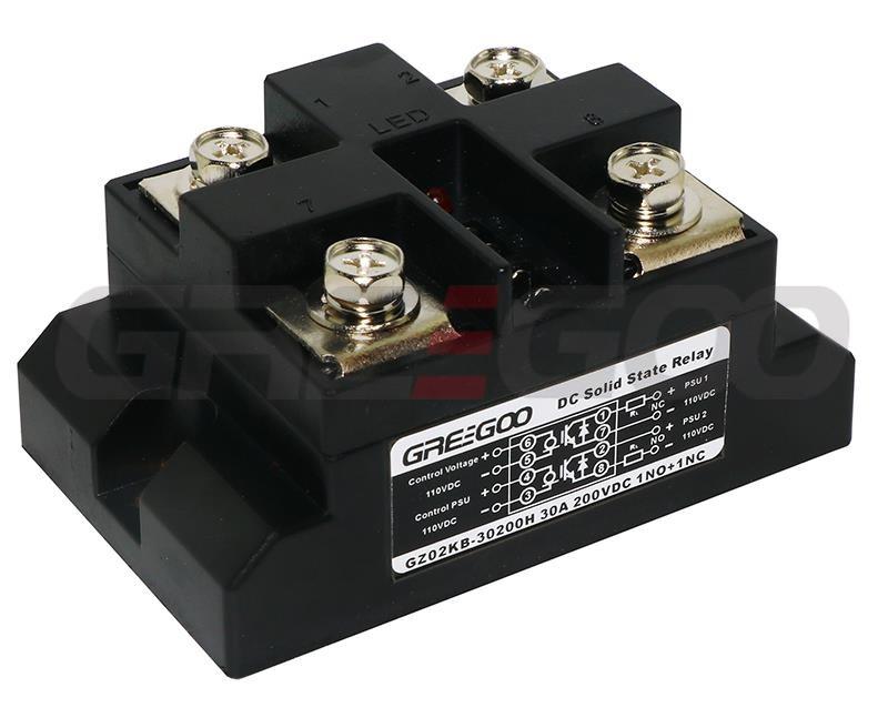
DC NC Solid State Relay GZ02BZ GZ02BF GZ08BZ GZ08BF
Home Products DC to DC Solid State RelayNormally Close (NC) DC Solid State RelaysDC NC Solid State Relay GZ02BZ GZ02BF GZ08BZ GZ08BF
Specification
DC NC Solid State Relay GZ02BZ GZ02BF GZ08BZ GZ08BF
| Model | GZ02BZ | GZ08BZ | GZ02BF | GZ08BF |
|---|---|---|---|---|
| Control Power | Connect to positive load power | Connect to negative load power | ||
| Drive Mode | Optoelectronic isolation | |||
| Control Signal | 4~32 VDC; 10~20 mA | |||
| Control Indicator | LED | LED | LED | LED |
| Load Voltage | 12-60V | 100-600V | 12-60V | 100-600V |
| Maximum Current | 20, 30, 50... 150 A for GDZ02BZ/F, 150, 200, 300, 400, 500, 600, 800,1000A for GDZ08B/F | |||
| On-state Voltage | ≤ 1 VDC | ≤ 3.5 VDC | ≤ 2 VDC | ≤ 5 VDC |
| Off-state Voltage | 100V | 1200V | 100V | 1200V |
| On-off Time | ≤ 0.2 mS | ≤ 0.25 mS | ≤ 0.3 mS | ≤ 0.35 mS |
| Switching Characteristics | MOSFET | IGBT | MOSFET | IGBT |
| Isolation Voltage | ≥1500V | ≥1500V | ≥1500V | ≥1500V |
| Insulation Voltage | ≥ 2000 V | ≥ 2000 V | ≥ 2000 V | ≥ 2000 V |
| Operating Temperature | -25 ~ 75 ℃ | -25 ~ 75 ℃ | -25 ~ 75 ℃ | -25 ~ 75 ℃ |
| Cooling Conditions | ≥30A with heat sink, ≥120A with fan cooling | |||
| Load Current Safety Factor | Resistive load: 2.5-3 times, Inductive load: 3-4 times | |||
Selection tips
- For resistive loads: Select the current at 2.5 to 4 times the load current, and the voltage at 2 to 3 times the load voltage. For inductive loads: Select the current at 3 to 4 times the load current, and the voltage at 2 to 3 times the load voltage.
- According to the relationship between load current and ambient temperature, when the ambient temperature is high or the heat dissipation conditions are poor, the current capacity should be increased.
- To prevent permanent damage to the solid-state switch due to load short circuit during use, it is required to connect a fast circuit breaker or fast fuse with a current rating slightly smaller than that of this product in series in the load circuit.
- For inductive loads, a freewheeling diode must be connected in parallel at both ends of the load, or an overvoltage protection absorber must be connected in parallel at the output end, such as a varistor (which can be selected at 1 to 1.5 times the power supply voltage), to prevent damage to the output transistor during overvoltage.
- When the load is connected to the positive power supply, select the GZ02BZ series; when the load is connected to the negative power supply, select the GZ02BF series.
- The normal on-off working sequence is to first connect the load power supply, and then apply the control signal voltage, otherwise, the internal chip is easily damaged.
- During installation, the contact surface between the heat sink and this product must be flat and smooth, and a layer of thermal grease should be applied to its surface. Finally, tighten and fix the screws with flat washers and spring washers symmetrically to improve heat dissipation performance.
Product Details
- Optical isolation between control signal and output circuit.
- Control signal interfaces with PLC and TTL logic signals.
- LED indicator for operating status.
- Solid-state normally closed output, fast switching speed, no spark or arc during switching.
- Epoxy resin encapsulation, corrosion-resistant, shock-resistant, stable and reliable switching.
- Mainly used for high-frequency DC-powered load electrical switches. Examples: DC motors, solenoid valves, heaters, and battery charging/discharging switches.
Inquiry
Need more information?
Contact us to request pricing, availability and customization options.


