Protective and Measuring Transformers for Medium-Voltage Equipment
Home Products Medium Voltage CT & PTMedium Voltage Current TransformersProtective and Measuring Transformers for Medium-Voltage Equipment
Protective and Measuring Transformers for Medium-Voltage Equipment
The task of instrument transformers is to transform high currents and voltages proportionally and in-phase into small current or voltage values for measuring or protection purposes. So they are used either to measure and record the transmitted power or to feed protection devices with evaluable signals, which enable the protection device to trip a switching device depending on the situation. Furthermore, they isolate the connected measuring or protection equipment electrically from live parts of the switchgear.
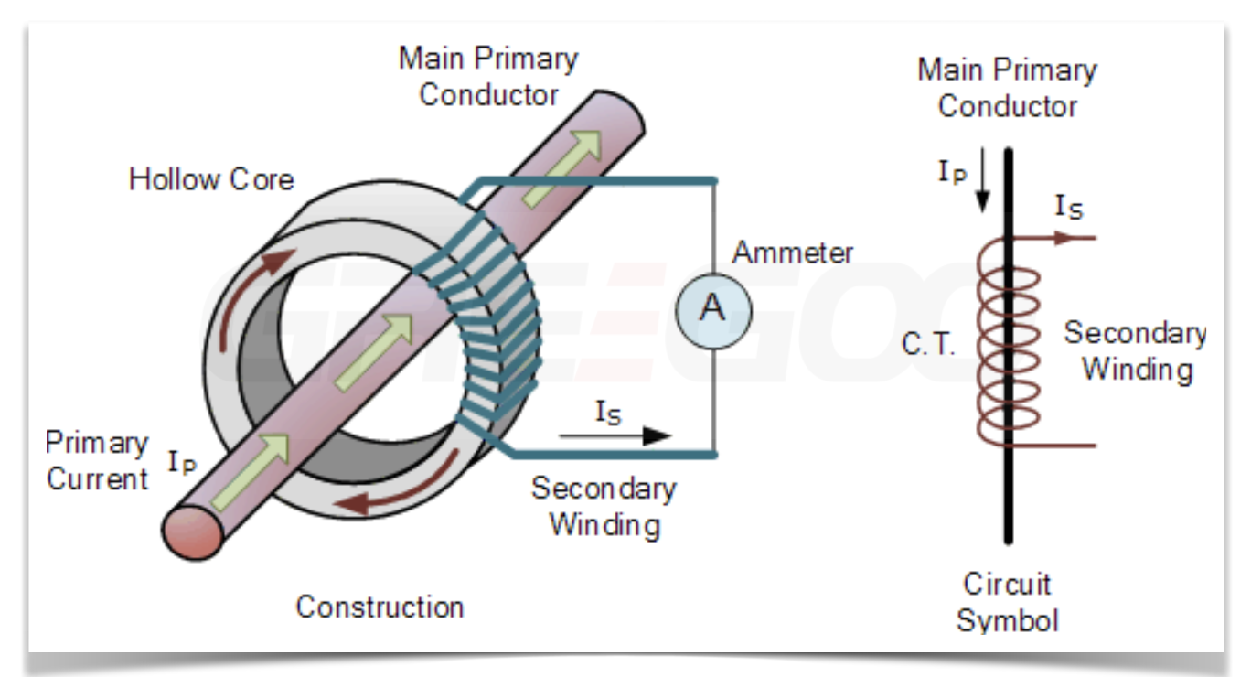
Current transformers can be regarded as transformers working in short-circuit, with the full normal current flowing through their primary side. Devices connected on the secondary side are series-connected. Current transformers can have several secondary windings with magnetically separated cores of the same or different characteristics. They can, for example, be equipped with two measuring cores of different accuracy class, or with measuring and protection cores with different accuracy limit factors. Due to the risk of overvoltages, current transformers must not be operated with open secondary terminals, but only in short circuit or with the burden of the measuring equipment.
Voltage transformers contain only one magnet core and are normally designed with one single secondary winding. If necessary, earthed (single-phase) voltage transformers are provided with an additional residual voltage winding (earth-fault winding) beside the secondary winding (measuring winding). In contrast to current transformers, voltage transformers must never be short-circuited on the secondary side. The earth-side terminal of the primary winding is effectively earthed in the terminal box, and must not be removed in operation.
Types of construction
Protective and measuring transformers are designed in different types of construction for the multiple installation requirements and operating conditions they are subjected to. They are electrical devices which convert primary electrical values – currents or voltages – into proportional and in-phase values that are adequate for the connected devices such as measuring instruments, meters, protection relays and similar.
Current transformers
•Indoor support-type current transformer in block-type design
•Indoor support-type current transformer in single-turn design (e.g. bar-primary transformer)
•Indoor bushing-type current transformer in single-turn design
•Indoor bar-primary bushing-type current transformer
•Outdoor support-type current transformer
| Operating voltage Um: | 12/24/40.5kV |
| Rated short-duration power-frequency withstand voltage Ud: | 42/65/95kV |
| Rated lightning impulse withstand voltage Up: | 75/125/185kV |
| Rated frequency: | 50/60Hz |
| Rated primary current IPN: | 5A to 4000A |
| Multi-ratio | 2x20 to 2x600 |
| Secondary current ISN: | 1/5A |
| Rated short time thermal current Ith: | 80kA or 100xIPN |
| Rated dynamic current Idyn: | 120kA or 2.5xIth |
| Core: | |
| Protection (Factor) | 5P10, 5P15, 5P20, 10P10, 10P15, 10P20 |
| Power Capacity | 10VA/15VA/20VA/30VA |
| Measuring (Accuracy) | 0.2/0.2S/0.5/0.5S/1/3 |
| Power Capacity | 10VA/15VA/20VA/30VA |
For example: Measuring only model 600A/5A, 0.2S, 10VA or multi-ratio 2x500A/5A, 0.2/0.5 10/15VA
Measuring with protection model: 600A/5A 0.2/10P10 10/15VA
Voltage transformers
•Earthed (single-phase) or unearthed (double-phase) indoor transformers in different sizes
•Earthed (single-phase) or unearthed (double-phase) outdoor transformers in different sizes
| Operating voltage Um: | 3.6/7.2/12/40.5kV |
| Rated short-duration power-frequency withstand voltage Ud: | 25/32/42/95kV |
| Rated lightning impulse withstand voltage Up: | 40/60/75/200kV |
| Rated frequency: | 50/60Hz |
| Rated thermal limiting output of the residual voltage winding: | 230VA/4A |
| Rated primary voltage maximum VPN: | 3kV, 6kV, 10kV, 40.5kV, 3/√3 V, 6/√3 V, 10/√3 V,40.5/√3 V |
| Secondary voltage USN: | 100V, 220V, 100/√3 V, 220/√3 V |
| Thermal limiting output Sth: | 200VA, 300VA, 400VA, 500VA, 600VA, 800VA, 1000VA |
| Auxiliary residual voltage winding | Without or 100/3V, 110V/3V, 120/3V |
| Rated output of the measuring winding | Class 0.2/0.5/1/3/5 |
| Rated output of the protection winding | 3P or 6P |
| Rated output of the power capacity | 10VA, 15VA,20VA, 30VA, 50VA, 60VA, 100VA,150VA, 200VA etc. |
For example: JDZ10-10A, 10/0.1KV, 100V, 0.2/30VA, Dual output voltage: JDZ10-10A, 10/0.1KV, 100/100V 0.2/0.5 10/15VA
JDZ10-10A 10/√3 / 100/√3 /100/3V 0.5/3P 15/20VA
 |
 |
 |
 |
|
Indoor support-type current transformer, Block-type design, Small type according to DIN 42600, Cast-resin insulated, Operating voltage up to 12 kV, 24 kV or 36 kV |
Indoor support-type current transformer, Block-type design, Large type according to DIN 42600, Cast-resin insulated, Operating voltage up to 12 kV, 24 kV or 36 kV |
Indoor bar-primary bushing-type current transformer, Cast-resin insulated, Operating voltage up to 12 kV, 24 kV or 36 kV |
Outdoor support-type current transformer, Cast-resin insulated, Operating voltage up to 12 kV, 24 kV or 36 kV |
 |
 |
 |
 |
|
Indoor voltage transformer, Block-type design, Cast resin type of construction according to DIN 42600, Double-phase cast-resin insulated, Operating voltage up to 12 kV or 24 kV |
Indoor voltage transformer, Block-type design, Cast-resin type of construction according to DIN 42600, Single-phase cast-resin insulated, Operating voltage up to 12 kV or 24 kV |
Outdoor voltage transformer, Large type of construction, Single-phase cast-resin insulated, Operating voltage up to 12 kV, 24 kV or 36 kV |
Outdoor voltage transformer, Large type of construction, Double-phase cast-resin insulated, Operating voltage up to 12 kV, 24 kV or 36 kV |
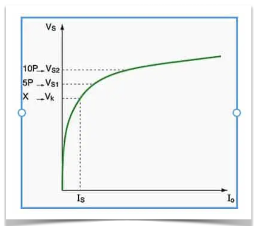
In a current transformer, "5P20" is a designation indicating its accuracy and overload capability. The specific meanings are as follows:
5P: This indicates that the accuracy class of the current transformer is class 5. The "P" stands for Protection, meaning that this transformer is primarily used for protection circuits. A class 5 accuracy means that under rated conditions, the transformer's error does not exceed 5%.
20: This indicates that the Accuracy Limit Factor (ALF) of the current transformer is 20. This means the transformer can maintain an accuracy within 5% even when the current is 20 times its rated current. This characteristic is crucial for protection equipment because, in the event of a fault, the current may increase significantly.
Overall, "5P20" indicates the accuracy and performance of the current transformer under high current conditions, ensuring that protection devices can accurately detect and respond during power system faults.
5P20 and PX class current transformers (CTs) differ mainly in their applications and performance characteristics:
|
5P20 Current Transformer Application: Primarily used for protection circuits. Accuracy Class: 5P indicates an accuracy class of 5, suitable for protection purposes, with an error not exceeding 5% under rated conditions. Accuracy Limit Factor (ALF): 20 means it can maintain accuracy within 5% even at 20 times the rated current. This is crucial for protection equipment that needs to accurately measure high currents during fault conditions.
Application: Mainly used for precision measurement and protection, especially in scenarios requiring high accuracy and linearity. Characteristics: PX class transformers do not have a fixed accuracy class but are defined by specific linearity, phase error, and other parameters. These transformers are typically used in applications requiring precise measurements, such as differential protection and distance protection. Design: PX class transformers are designed with a focus on linearity and phase characteristics to ensure accurate measurements under various load conditions. |
 |
In summary, 5P20 transformers are more suitable for general protection applications, while PX class transformers are used in scenarios requiring high precision and specific performance. The choice between them depends on the specific application needs and system requirements.
PX class current transformers (CT) specifications are typically defined based on their linearity, phase error, and other specific parameters. Here are some common specifications and characteristics of PX class CTs:
Linearity: PX class CTs should maintain good linearity within their rated current range to ensure measurement accuracy. This means that the relationship between the output current and input current should remain linear under different current loads.
Phase Error: PX class CTs should have minimal phase error to ensure accurate phase relationships between current and voltage when measuring AC current. This is crucial for the precise operation of protection devices.
Rated Current: The rated current of a PX class CT is the standard current value it is designed to measure. The CT should provide accurate measurements at this rated current.
Rated Load: This refers to the maximum load (usually measured in VA) that the CT can handle on its secondary side while still maintaining its accuracy.
Insulation Level: PX class CTs should have sufficient insulation levels to ensure safe operation under high voltage conditions.
Thermal Stability: The CT should be able to withstand short-term overcurrents without damage, which is particularly important for protection applications under fault conditions.
Frequency Range: PX class CTs are typically designed for a specific frequency range (e.g., 50Hz or 60Hz) to ensure optimal performance at that frequency.
These specifications ensure that PX class current transformers can provide reliable performance in high-precision measurement and protection applications. Specific specifications may vary depending on the manufacturer and application requirements, so detailed specification confirmation should be conducted based on specific application needs when selecting PX class CTs.
A medium voltage current transformer is a device used to measure and monitor current in medium voltage power systems. Its main function is to convert high current into a smaller, manageable current for measurement and protection of the power system. Medium voltage current transformers are typically used in power transmission and distribution systems to help ensure the safety and efficiency of the system.
These transformers operate on the principle of electromagnetic induction and usually consist of a primary winding and a secondary winding. The primary winding is connected to the high current circuit, while the secondary winding outputs a smaller current proportional to the primary current. This smaller current can be safely used by measuring instruments or protective devices.
Medium voltage current transformers play a crucial role in power systems, ensuring the accuracy of current measurement and the safety of the system.

Need more information?
Contact us to request pricing, availability and customization options.


